Product Code: LBNY-0005-12500099
Categories: Thermal Engineering and HVAC Equipment
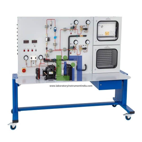
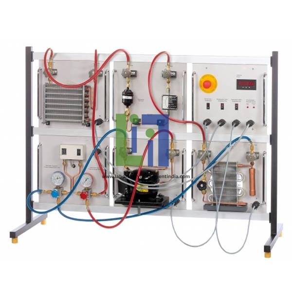
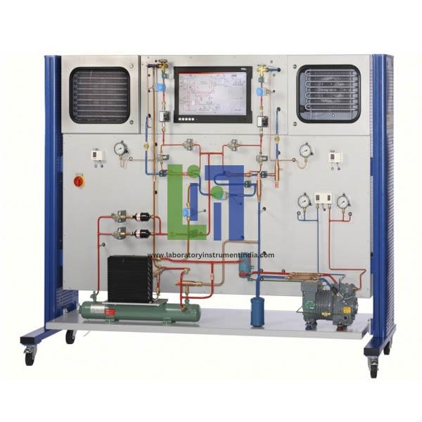
Refrigeration circuit with compressor, condenser, capacity controller, start-up controller, combined pressure switch and 2 evaporators in insulated chambers
Refrigeration chamber with evaporation pressure controller
Freezing chamber with electric defrost heater and hot gas defrosting
Separate or parallel operation of the chambers via solenoid valves
Simulation of 12 faults
Each chamber with solenoid valve, thermostat, thermostatic expansion valve, fan and heat exchanger for refrigerant supercooling
Investigation of a refrigeration system with refrigeration and freezing chambers
Touch panel pc for fault activation, data acquisition, evaluation and representation in the
Refrigerant R404a
Log p-h diagram
Evaporator Transfer Areas
Capacity controller: 0,2...6bar
Start-up controller: 0,2...6bar
Refrigeration chamber: 1,12m²
Electric defrost heater: approx. 125W
Thermostat: 2x -25...15°C
Freezing chamber: 1,88m²
Evaporation pressure controller: 0...5,5bar
Compressor
Refrigeration capacity: 2440W at -10/30°C
Volumetric air flow rate: 570m³/h
Condenser With Fan
Measuring Ranges
Flow rate: 2x 1.5...22,5l/h
Compressor power consumption: 0...5kW
Temperature: 6x -50...50°c; 5x 0...100°c
Pressure: 3x -1...12,5bar; 2x -1...24bar.
Similar items like Capacity Control And Faults In Refrigeration Systems you may view