Product Code: LBNY-0005-12500038
Categories: Thermal Engineering and HVAC Equipment
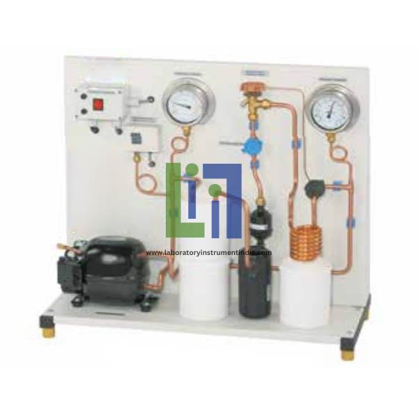
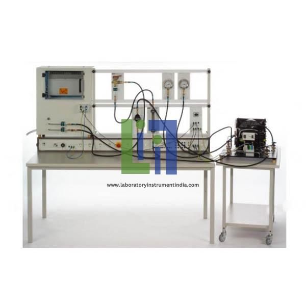
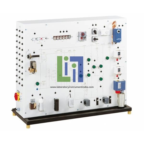
Demonstrates the electrical circuit of a complex full conditioning system with heat pump function. The control circuits are actually present. The components in the load circuits are simulated (e.g. compressor, heater, 4-way reversing valve). Identifying electrical faults in air conditioning systems requires comprehensive knowledge. This knowledge includes the design and operation of the individual electrical components as well as the reading of circuit diagrams. Helps to acquire this knowledge. At very low outer temperatures an electrical auxiliary heating is activated during heating operation. With low air humidity the hygrostat activates the humidifying function. The air conditioning system with heat pump function cools in the summer and heats in the winter. During heating operation the defrost timer introduces a hot gas defrosting by briefly switching the 4-way reversing valve. The operating state of the simulated components is indicated via lamps in the circuit diagram on the front panel. Typical protection devices, such as circuit breaker and frost protection monitor, complete the electrical circuit.
Experimental unit from the practical series for the training of mechatronics engineers for refrigeration
Real control circuits with electrical components, simulated load circuits
Circuit diagram depicted on the front panel
Identification of 30 faults: multimeter measures voltages or resistances at the lab jacks
Humidifier with hygrostat, solenoid valve and float switch (pump simulated)
Hot gas defrosting by switching the 4-way reversing valve
Operating states of the simulated components indicated via lamps in the circuit diagram
Simulation of the electrical circuit of a complex conditioning system with humidifier and heat pump function for heating, cooling and humidifying.
Similar items like Electrical Faults In Full Air Conditioning Systems you may view